Time: 2020 Spring
Team Size: 2
Role: engineer, electronic circuit designer
Tools: EAGLE, LM324, LEDs, resistors


Sound of Rainbow
Physical Computing
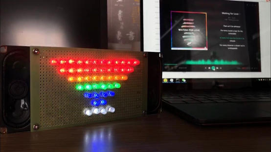
This is a music visualization speaker. The device is comprised of LED lights, a perfboard, a speaker, and some cables to connect to an audio source. The LED formation will react to the input audio's volume.
This serves as an exploration of crossing the boundary of human senses. The project is part of a series of experiments utilizing LED. Other experiments see "Butterfly Lights".
Inspiration
Theremin, speaker, and Maxwell Equations.
The starting point of this project is a speaker, which is one of the most common applications of electromagnetic theory. The principle behind the speaker is that there is a coil attached to the diaphragm of the speaker. And there is a magnet placed just near the coil. When there is current flowing through the coil, according to the fact that flowing current can generate a magnetic field, the magnetic field of the coil and that of the magnet will attract or repel each other. This force will thus generate minute vibration on the diaphragm, which then generates the sound that we can hear. This process can be quantified by one Maxwell equation (see right).
Me and my partner took a deep look at this whole process and discovered that, when the sound is generated, the loudness is related to the strength of the current that is flowing through the coil. So we came up with the idea of creating a Volume Unit meter that is composed of LEDs to partially represent this magnificent electromagnetic phenomenon.


Process
Experiments, fabricating the project, audio jack, and speaker.
Experiments: design the circuit, voltage calculations, several problems and adjust resistors values

To start off, we gained tremendous support from the artist GreatScott. On that basis, we set up a test circuit (See left). We developed the minimum test case for the circuit to make sure it works as expected. At the minimum, everything maintains the same principle as the complete diagram that we would be following. The components included are:
-
2 x LM324 Amplifiers
-
1 x Voltage Regulator
-
7 x IRFD220 N-Channel MOSFETs
-
7 x LEDs (One for each row)
-
1 x 4Ω8W Speaker
-
1 x 3.5mm Audio Jack
-
Resistors
To avoid unexpected situations in real production, I designed some testing and experiments. The experiments I’ve conducted mainly contain two parts; fabrication-wise experiments and circuit-wise experiments. For the fabrication-wise experiments, since I want our final project to be aesthetically pleasing, I need to make sure every single component is in its designated place. I tried to draft on the perfboard with different combinations and solutions to select the best one (See right).
Then I built this minimum test circuit to verify the design of the circuit and try to find out potential issues. I found out that the resistors that are used to filter the signal are too big for phone audio output as the source. These 10K Ω resistors are applied for an input source of peak voltage at around 1.5V. My partner and I measured our audio sources and discovered the peak output voltage is around 0.3V. Even though the volume on the phone is already at its maximum, it was still not enough to power all the LEDs.
To sort that out, I removed these two 10KΩ resistors (See right). With the new value, I brought them into the LM324 op-amp circuit to test. I wanted to reduce the power consumption on mobile devices so I turned the volume to around 50%. That lowers the voltage of the audio signal to around 0.15V. Since the LED array I am using has 7 lines, I want to control our amplified signal voltage around 7V.
In the LM324, I applied a non-inverting op-amp to the audio signal. With the current resistors setup, the total gain of the audio signal is 48 (See right). I multiplied 48 by 0.15V, which gives us 7.2V, just over the voltage I need.
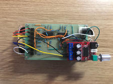
After re-designing the circuit, the completed test circuit looks like this (See right). I completed this circuit on the breadboard and the seven LEDs worked properly, so I continued my work and expand it into more LEDs and on a perfboard.

.png)


Development: soldering, compact speaker and audio jack
.png)
1. Design the component layer circuit on the perfboard (see left).
In the diagram, the grey lines represent tin and the redlines represent live wire while the black ones represent ground wire. The two orange wires are reserved for the input audio signals from the audio source devices. For the audio signal amplified LM324, I connected them internally with tin so that I do not need to hook up other wires. (To keep the diagram as neat as possible, the hookup wires from the output of LM324 to the NMOS gates are not shown on the diagram.)
2. Soldering components and LEDs.
I basically followed the components layout as in the test circuit, just transforming it onto the perfborad. My partner and I designed two layouts for the LEDs (See right). We chose the second design in the end as it indicates the increase in volume by the number of LEDs per line.
I soldered everything by hand, and the back of the perfboard looks like this (See right). After combining the audio jack and the speaker, the project looks like the this (See right).
_edited.jpg)

.png)

Feedback & Reflection
After showcasing the project to my class, my family and friends, and at the Interactive Media Show, I received feedback being:
[Positive]
1. The project is a transformation to our daily practical item: speaker. It is aesthetically pleasing: the rainbow of LEDs. And the concept "sound of the rainbow" could provoke more insights into the project.
2. The project is really pretty and practical at the same time.
[Negative]
1. More fabrication to the speaker and the board would be ideal since this is a both practical and aesthetically pleasing project.
2. Instead of making the LEDs illuminate according to the volume of the music, a frequency spectrum made of LEDs would be more intriguing and reveal more details about the music.
3. Maybe try the LED strip / full color LED that could change color accordingly to make it more dynamic and interactive.
4. Instead of using perfboard, try designing a PCB board that would be much neater and easier to deal with.
5. Maybe add a screen before the LEDs to make it more complete and look like a real speaker.
Since this project is done in my home during the pandemic, there were a lot of constraints of equipment, environment, and teamwork. The project only serves as a straightforward approach to visualize music and an experiment to endow daily objects such as speakers with new meanings. My goal is primarily achieved but could be further implemented.
However, due to the inconvenience of transferring the project back to the campus studio, I have to cease the implementation of the project. But I carried on what I learned from the project into other physical computing projects (See butterfly).